The motherboard is the foundation of the entire system. It is selected based on the processor, while all other components are universal and can be connected to any motherboard.
The socket and chipset support for a specific processor is the main criterion for choosing this system element. Compatibility with the power supply and memory is also important, followed by cooling and the quality/presence of additional modules such as a sound card, Wi-Fi/Bluetooth, additional network port, etc.
Processor Compatibility
Matching the socket on the processor and motherboard does not necessarily mean compatibility; the motherboard might not support your CPU model. Pay attention to the chipset - older chipset models might not be able to work with a new processor model. To ensure compatibility, check the motherboard specifications.
If you can't find this information, compare the chipset model with your processor. This can be done on official websites:
- Intel – processor support by chipset or search for compatible solutions for the processor.
- AMD – check the AMD Ryzen chipset version.
Unfortunately, AMD does not have convenient tools for finding compatible solutions. However, they also did not produce such a variety of lines that are incompatible with each other, like Intel.
Understanding AMD processors is much simpler; they only have two current sockets for desktop motherboards – AM4 (mainstream) and TR4 (high-end solutions). Intel, on the other hand, currently has several relevant sockets, such as 1150, 1151, 1151 v2, and the latest 1200, as well as alternative sockets for high-end solutions - 2011-3 and 2066. Each socket has about 3-5 chipsets, which do not support all models on their socket. Therefore, compatibility must be checked in the technical documentation of the motherboard.
Power Supply Compatibility
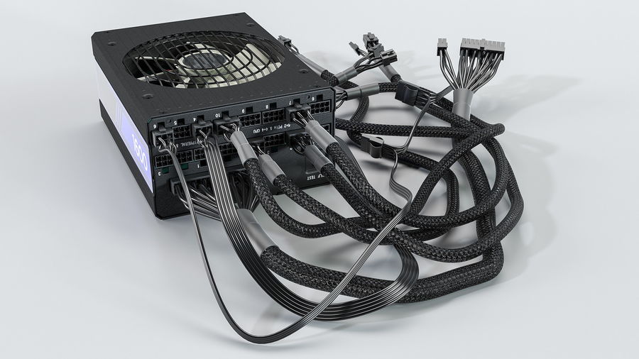
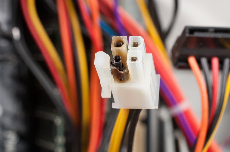
Another parameter for choosing a motherboard is the power connector for the board and the processor. Power supplies can have soldered wires or be modular (as in the photo).
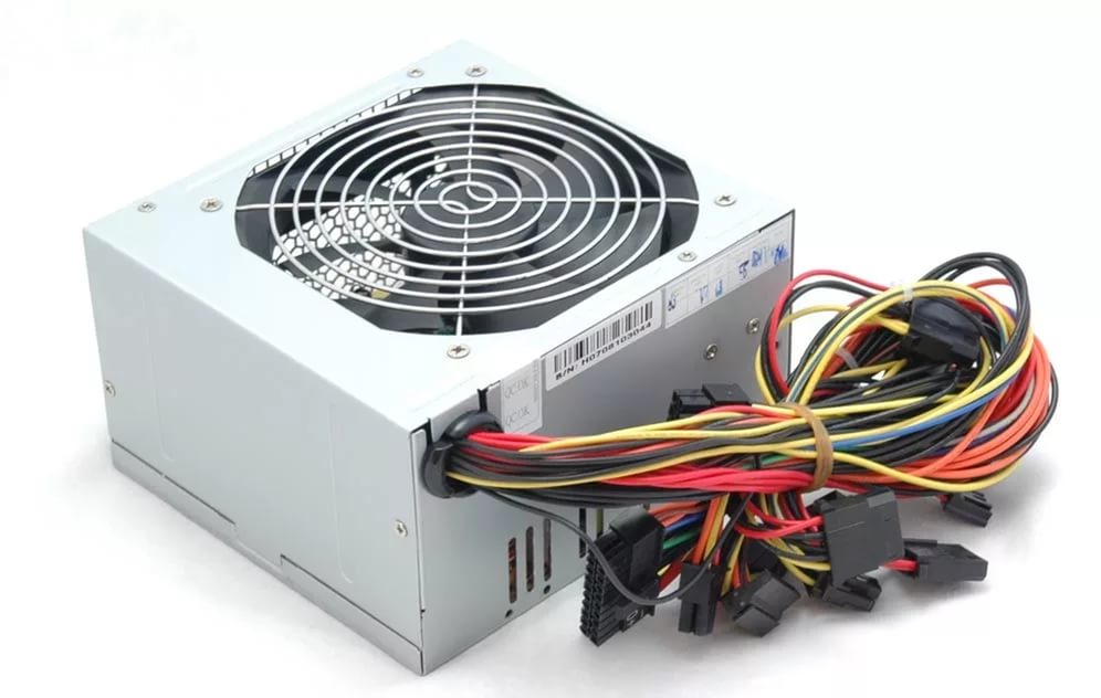
If the wires are soldered, you won't be able to change the connectors. Adapters can be used, but there are some drawbacks. The first drawback is the reduction of power connectors as they will be occupied by adapters for powering the board.
The second disadvantage of this type of connection is unreliability; adapters may have poor contact or simply disconnect during operation. In the best case, the computer will turn off; in the worst case, the motherboard will burn out. So, if the power supply is not suitable for the motherboard connectors, it is better not to use it.
Modular PSUs are a bit more expensive than standard ones, but these costs are justified. There are several reasons for this:
- Aesthetics. No extra wires hanging in the case, no need to hide and tie them. You can choose the length of the wires, repack the connector with other wires, or simply buy ready-made ones. In modern cases with bottom-mounted PSUs, you will hardly see the wiring as it can be completely hidden behind the motherboard or in special channels if provided by your case.
- Air circulation. Hanging wires not only affect aesthetics but also significantly slow down the airflow in the case. Fans work harder, and the airflow is worse due to many obstacles creating interference for the air current.
- Less dust. Wires in modern electronics are made of copper. If they are near an active circuit with current flowing through it, an electromagnetic field is created, attracting dust. This effect can be observed on the transistors and capacitors of the power supply – despite good insulation, they will always be covered in dust, which can only be blown off with a strong air stream or cleaned with a brush.
Most common motherboards have 20 Pin and 24 Pin power connectors, and most power supplies have a 20+4 Pin output, which means you can combine them to get 24 Pin or use them separately.
With such boards, you are unlikely to have any problems, but there are specific motherboards with 12 Pin power connectors, which are not provided by PSU manufacturers. The solutions to this situation are either using an adapter or buying the plug and rewiring according to the pinout scheme.
CPU Power on the Motherboard
CPU power connectors vary. The simplest is 4 pins, followed by 6, 8, 6+4, 8+4, 8+8. The number of pins is determined by how much power the CPU needs during operation.
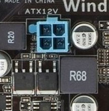
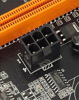
What happens if you connect only 4 Pin instead of 8 Pin?
Nothing good. To avoid seeing what is shown in the photo, you need to connect all connectors to their proper places.
To understand the processes, you need to know what electricity is and how it works. To avoid describing an 8th-grade physics course, let's simplify.
The more amperes (A), the thicker the wires needed. Power in watts (W) is determined by the power consumption of the connected device. Watts are amperes multiplied by volts (V). To transmit 1000 watts of energy per hour at a network voltage of 220 volts over 10 meters, a copper wire with a diameter of 1.38mm is needed. If we use a 12-volt network and want to transmit the same amount of energy, we need a copper conductor with a thickness of 5.64 mm.
It's all about the number of amperes. If we need only 4.5A at 220V, then at 12V – 83A. An ordinary computer processor operates at a voltage of 1.1 to 1.7 volts and consumes 65-135 watts. For example, the Intel Core i7-11700K has a peak power consumption of 125 watts at standard frequencies. When overclocked, it works with these parameters – 1.36V at a power consumption of about 310 watts.
Using simple math, we get a figure of 227A, not every welding machine can provide such a number of amperes to the electrode. Household welders range from 120 to 200A. Another example – 200A is the upper limit at which a 5mm thick electrode melts. Such electrodes are used for welding metal up to 16mm thick. Although the voltage on the welding inverter is higher (40-80V), the voltage conversion scheme on the inverter is very similar to the one found on the motherboard.
To prevent the motherboard from melting and to avoid using finger-thick wires, it consumes 12V and transforms it as close to the processor as possible to provide the required voltage level.
Therefore, it is crucial to ensure good airflow and a sufficient number of parallel power lines. This means you cannot connect a splitter to a single connector; they are only suitable for drives and peripherals. Separate wires from the power supply must go to the CPU and graphics card – power should not be split between two such power-hungry connectors.
RAM Compatibility
This is much simpler; RAM differs by version – DDR3 or DDR4. The third version is actively dying out, the fourth is taking over the world, and soon we will be introduced to DDR5. They are not compatible at all, and it is not necessary. The main thing is to match the frequency. That is, the maximum allowed memory frequency on the motherboard and processor should match the default settings of the RAM sticks you are installing.
It is advisable not to install memory sticks from different manufacturers or with different timings on the same motherboard. If there is no other choice, you should divide them into different channels. Distribute the memory sticks so that they are in different channels, even if they are identical, this way you will increase the speed of data writing and reading.
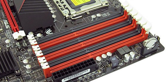
The logic is simple – most desktop processors have two memory channels, and some high-end models can work with four channels, so there may be 6 or even 8 slots, but the number of channels is limited. If you put two sticks in one channel, they will have to use the bandwidth of one channel together.
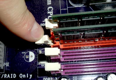
Memory channels on the motherboard are color-coded, as seen in the photo – a board with six slots and two channels.
Processors with 4 Memory Channels
Among modern models, only Intel Core i9 and i7 X series support four memory channels. From AMD's lineup, it's the Ryzen Threadripper 3000. All of them are quite expensive and belong to the high-end segment. In a gaming computer, you can easily do without such power.
These processors have their own socket, and motherboards for them are made with four channels and 8 slots, in rare cases, there may be up to 16 slots.
Motherboard Form Factor
Currently, there are about three dozen types of motherboard form factors. Here is an approximate list:
- AT (Advanced Technology) – one of the first form factors for desktop computer motherboards. Standard size 305 x 305 mm.
- ATX (Advanced Technology Extended) – the most widespread format that has taken over the world of computer building. It is most commonly used in desktop PCs. The main advantage of the format has always been the ability to place any modules on the back of the board without forcing case manufacturers to adjust their products. The familiar IO Plate, which comes with the motherboard for installation on the back of the PC case, was not always standard. The adopted board size is 305 x 244 mm, but there are others in smaller and larger sizes.
- CEB (Compact Electronics Bay) – a form factor for motherboards used in servers, mainly by Intel, Dell, and IBM. Not used in regular computers. Size – 305 x 267 mm.
- DTX – a socket created by AMD to reduce production costs. This board format allows dividing an industrial PCB blank into boards without trimming. Fully compatible with ATX mounting. Standard size – 203.20 x 243.84 mm.
- EATX (Extended ATX) – an enlarged ATX that allows placing more modules on the board, particularly more PCI slots. Standard size – 304.8 x 330.2 mm.
- FlexATX – one of the most compact motherboard sizes, being a reduced version of MicroATX, often with a limited number of expansion slots. These motherboards often have a built-in WiFi/Bluetooth module. Standard size – 229 x 191 mm.
- FullATX – not a form factor; it made the list only because case manufacturers indicate full compatibility of their product with all ATX formats this way.
- Mini-ITX – a small board format that replaced ITX, which was hardly used and is not even on this list. Standard mini-ITX size – 170 x 170 mm.
- Mini-ATX – small boards measuring 284 x 208 mm.
- Mini-STX – very small boards for mini-PCs or all-in-ones, with a standard board size of 140 x 147 mm.
- XL-ATX (Extra Large ATX) – a format of enlarged boards used in high-end computers to accommodate many modules in one system. Different manufacturers have dimensions differing by 2-3 mm in each direction. The largest format is from MSI, these guys cut PCB at 345 x 264 mm.
- MicroATX – wide boards with a small length but wider than FlexATX and MiniATX. Standard size – 244 x 244 mm.
- WTX – huge boards measuring 356 x 425 mm. Used as motherboards for servers on the Intel Xeon platform.
Comparison of Motherboard Form Factors
To make it easier for you to understand, look at the picture. Decoding:
- Red – FlexATX (229 x 191 mm)
- Orange – microATX (244 x 244 mm)
- Yellow – Mini ATX (284 x 208 mm)
- Green – standard ATX (305 x 244 mm)
- Blue – Extended ATX (EATX) (305 x 330 mm)
- Purple – WTX (356 x 425 mm)

How to Replace the Motherboard
You will need the following set of tools:
- Small and large Phillips screwdrivers.
- Clean cloth and alcohol for cleaning components.
- New thermal paste for installing modules.
- It is advisable to have tweezers, as not all motherboards have all elements within reach.
- A container for screws to avoid losing them.
- Flash drive, disk, or any other storage device with drivers for the new motherboard. If you don't download the network driver in advance, there is a chance that the system will not be able to connect to the internet, as it may not be able to work with the new network adapter.
Important! Do not use a screwdriver, as high rotation speed and power can easily damage delicate components on the board if the bit slips. It is acceptable to use cordless screwdrivers like Xiaomi Mijia Electric Screwdriver or Bosch IXO IV. They do not have high rotation speed and their power is significantly lower.
Steps for Replacing the Motherboard
The motherboard is the basis of the entire computer and everything is connected to it. Before removing it, be sure to disconnect the power. Disconnect all wires from the back of the case, unplug everything from the mouse to the monitor, there should be nothing left.
Remove the Case Cover
We are interested in the left cover when looking from the front of the case. Unscrew the screws (they are at the back) and slide it to the left, it will easily detach from the case. If your case cover is glass, it is fastened with four screws around the edges. They can be either for a screwdriver or knurled to be unscrewed by hand.
Remove the Graphics Card
It is screwed to the supporting bracket. There may be a screwless clamp, but it is definitely attached to it. Do not forget to release the latch on the PCI-E slot: if you do not do this, you can easily damage both the motherboard and the card itself.
More detailed instructions can be found here.
Disconnect Power Connectors and Fans
Remember that power connectors always have a latch that securely fixes them in the socket, be sure to release it when disconnecting. Although the connectors are reliably soldered, the plastic casing of the contacts can be easily removed, hold the mount with your hand or use a lever on the plug, using tweezers or a knife.
Also, disconnect all connected fans. If they are connected directly to the power supply via MOLEX, they should also be disconnected.
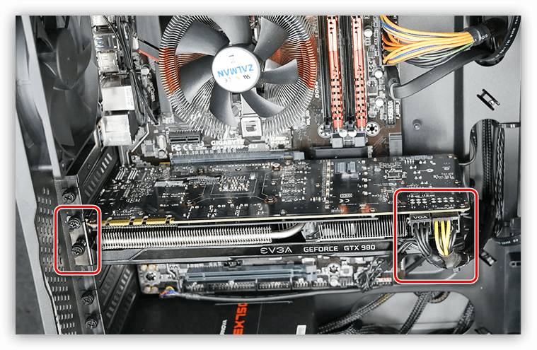
Remove the Power Supply
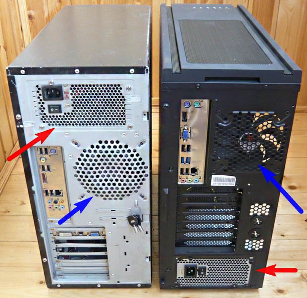
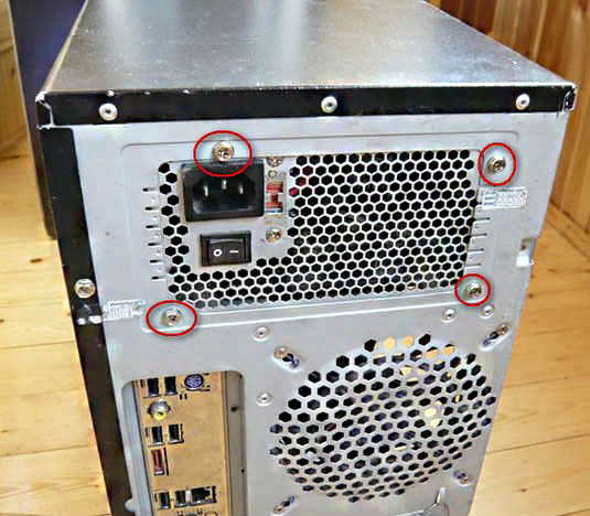
In most cases, it does not interfere with motherboard replacement, but to make it more convenient to use a screwdriver, it is better to remove it. Unscrew the screws on the back cover of the system unit. In the photo, the power supplies are shown in the case with top-mounted PSU (left) and bottom-mounted PSU (right) with red arrows. They are fastened with four screws – unscrew and remove them.
Important! The power supply is one of the dustiest places in the computer, as there are many magnetic fields that attract dust. If you have removed it, it is better to open the cover and blow it out with compressed air or at least clean it with a brush, after cleaning it will work quieter and heat less.
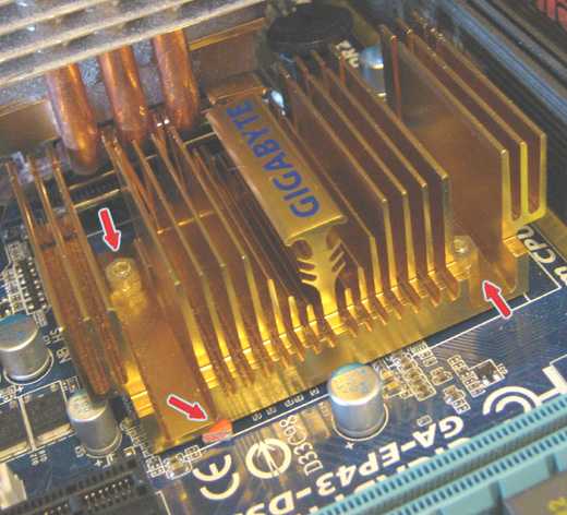
Remove the CPU Cooler
Release the retention mechanism if you have AMD, or turn the 4 plastic clips if you use an Intel processor. If you have an expensive cooling system with many tubes, it may be attached to a reinforcing plate with screws. In this case, you need to unscrew the screws to remove the cooler.
After removing the cooler from the processor, you need to clean the cooler and the processor cover from thermal paste, it cannot be reused, and if left, it can stain something.
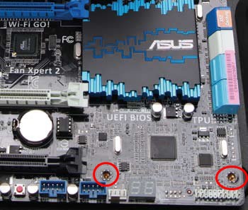
Remove the Processor
To do this, you need to release the lever and take it out of the socket. If you have AMD, it will fall out immediately, so it is advisable to perform all these manipulations with the motherboard lying on its side so that the processor does not fall to the floor or into the case. If this happens, it can be damaged, or the contact pins can bend, or even break off.
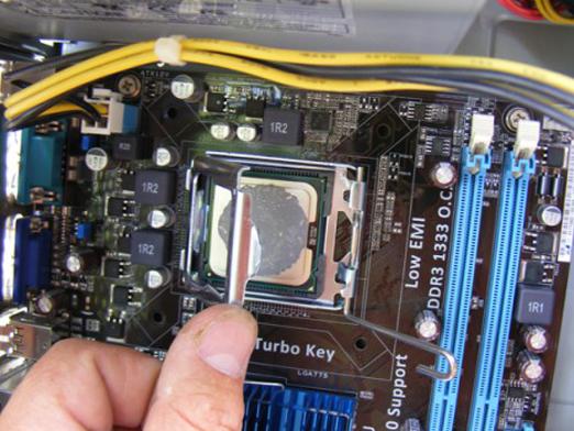
Intel processors are clamped with a metal frame (in the photo). After releasing the lever, you need to open the clamping frame.
Remove the RAM Sticks
Press the plastic latches on the sides of the stick, and it will pop out of the socket. It is best to press them simultaneously to avoid skewing the stick, but it is not critical. If the computer is old and has not been cleaned for a long time, there may be dark spots on the RAM contacts, which can be easily removed with alcohol and then wiped with a regular pencil eraser. After cleaning, the contact will be better and more reliable.
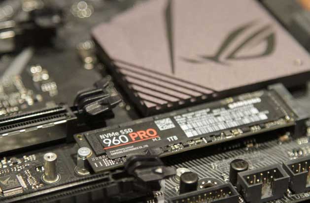
Disconnect the NVMe Drive
If you have one, of course. Unscrew the screw and remove the board from the socket.
Remove the Motherboard
You may still have connected fans or drives, which were inconvenient to access. But now you need to disconnect absolutely all wires.
To remove the board from the case, you need to unscrew the screws. Different boards may have a different number of screws, depending on the form factor; unscrew all of them.
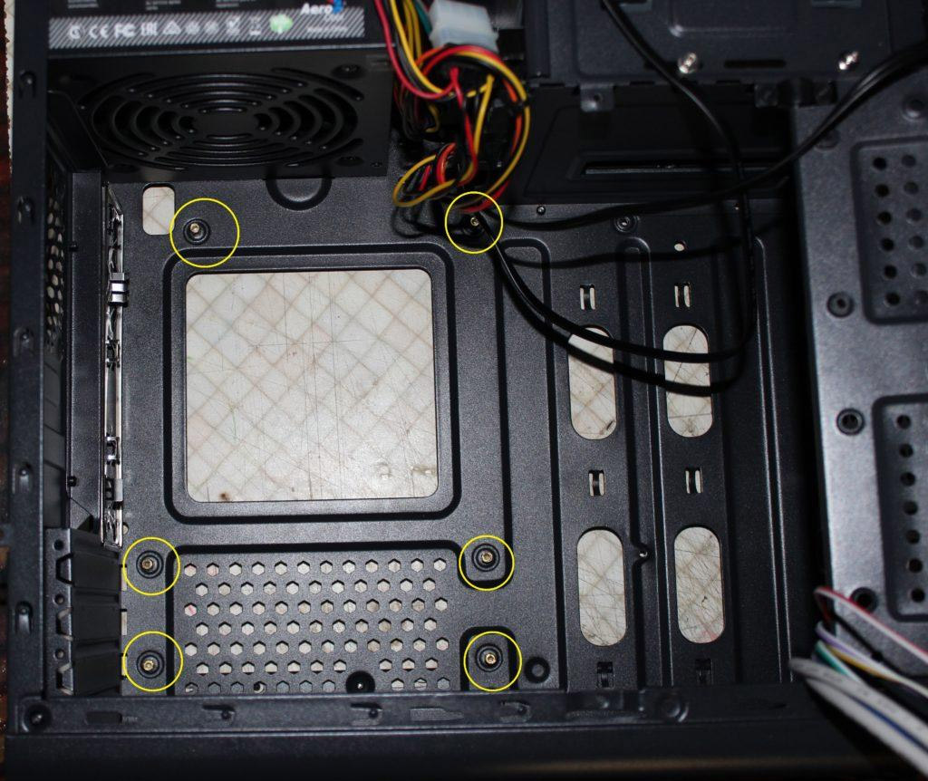
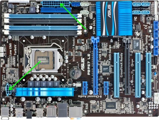
Important! Do not unscrew the chipset radiators. They are directly attached to the motherboard and do not participate in securing the motherboard to the case.
In the photo – chipset radiator mounts and holes for motherboard mounting screws. We need only the latter; they are outlined and have reinforcement at the contact point with the screw head.
The final step will be removing the backplate from the back of the case. It is attached with clips; you need to pry them from the back of the case and push it out from the inside. Do not apply force, the weak thin metal of the case is easy to bend, and it will be difficult to straighten it back neatly, most likely a dent will remain.
Installing a New Motherboard
You need to repeat all the same steps in reverse order. Remember that it is better to connect all inconvenient connectors first, and only then close them with a massive CPU cooler, RAM sticks, and graphics card.
The new motherboard does not require any actions from you, it is already ready for installation, just make sure you do not mistake which side to install it. To avoid such an error, remember – the processor is always on top, and the PCI-E slots are at the bottom.
When and How to Install the Backplate?
You can install the backplate at any time; it snaps in from the outside and does not require access to the back cover from inside the case. Just align the cutout holes with the outputs of the already installed motherboard and press firmly until a characteristic click. The plate should fit into place without any problems; all of them are standard.
What to Do After Replacing the Motherboard
Windows 10 handles replacing any hardware well and should boot in any case. However, there are several nuances related to licensing, which is tied to the MAC address of your computer, making it impossible to use it after changing the configuration.
To keep your user license, you need to create a Microsoft account and link it to your computer. This can be done by going to Windows settings – "Accounts".
Then you will be asked to sign in or create a Microsoft account. Follow all the registration steps. It is essential to link your email and phone number, accept the code, and enter it. Only then can you activate the account and link it to your mobile device to restore your key after changing the system configuration.
Then go back to the main settings page and click on "Update & Security", then "Activation". Click "Add an account" and enter the required information.
Now go to "Control Panel" – "Update & Security" – "Activation" and click on "Troubleshoot". Select "I changed hardware on this device recently", click "Activate". After these steps, your license will be saved and linked to your Microsoft account, allowing you to restore it at any time.
Replacing the Motherboard on a Laptop
Replacing a motherboard on a laptop is more complicated than on a desktop, as you will need to completely disassemble your laptop. The difficulty lies in the fact that each laptop model disassembles differently. It is best to have another device with a video of disassembling your device at hand. This will help you understand how to disassemble and reassemble the laptop. Moreover, assembling it is much more difficult than disassembling.
Laptop boards are not standardized like desktop PCs, so you need the exact same board as you already have. Exceptions can be models in the same case with different power and slots. In this case, it is often possible to install a more advanced motherboard in a simple case. But you need to know for sure that it will fit.
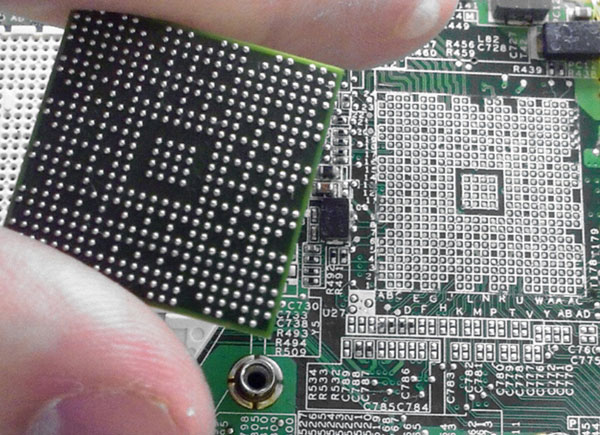
Another nuance is that the processor and graphics card are not always connected to the motherboard via a socket. Sometimes they are soldered (as shown in the photo). The point is that manufacturers usually do not need to install a socket and solder legs to the processor for contact, it is easier to rivet the board on just one solder and sell the finished device this way. Very few laptop models use a removable processor and graphics card.
If you are wondering if you can solder the processor yourself, the answer is definitely no, you cannot. To remove the processor, you need an infrared soldering station. The cost of a decent one goes far beyond a thousand dollars, and the simplest ones start at 500$. In addition to this equipment, you need skills; it will not remove the chip for you.
To solder the processor back, you need solder in balls of the appropriate diameter and a stencil for applying it.
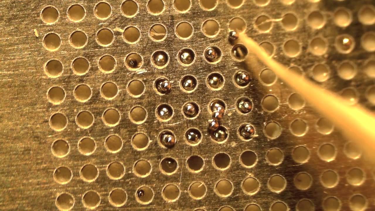
When each ball is in place, you need to heat the solder and melt it, thus tinning the contacts. Then you need to align the processor with its place on the board and send it for soldering to the soldering station.
Such actions require a professional approach; it is very easy to short the processor outputs during installation or simply burn the board along with the chip.